Difference Between Burnishing and Polishing A Tool Perspective

When refining concrete, terrazzo, or stone floors, the terms "burnishing" and "polishing" are frequently confused, but they represent distinct finishing techniques, particularly regarding the tools used. Recognizing these differences is crucial for choosing the appropriate method to achieve the desired look and durability of the surface.


Polishing is a detailed mechanical process that involves multiple steps with progressively finer abrasives to eliminate scratches and create a smooth, shiny finish. It usually begins with metal diamond grinding tool for grinding, followed by resin polishing pad. These tools penetrate the surface layer, gradually enhancing it to a high-gloss finish. The focus of polishing is on improving surface flatness and clarity, making it a common choice for preparing floors in retail, commercial, and upscale residential environments.


In contrast, burnishing is more of a maintenance procedure rather than a material removal technique. It employs non-aggressive pads—often diamond-impregnated or fiber polishing pads—operating at high speeds to heat the surface and enhance its natural shine. Unlike polishing, burnishing does not remove material; instead, it improves the appearance of an already polished floor. Diamond burnishing pads are particularly favored for maintaining the shine of polished concrete without disturbing the surface.


Diamond burnishing pads


The difference in tool selection highlights the practical distinctions between the two methods. Polishing necessitates a range of tools with varying grit levels, such as resin-bond pads from 50 to 3,000 grit. Burnishing, however, typically requires fewer tools—often just a single high-speed machine with a burnishing pad that interacts with the surface through friction and pressure. This makes burnishing a quicker and more cost-effective option for regular maintenance.


While both techniques enhance the visual appeal of floors, polishing is about transformation, whereas burnishing focuses on preservation. Understanding when to use each method can help prevent unnecessary wear and reduce maintenance expenses. Choosing the right tools for each process ensures both effectiveness and long-term surface protection.

Top Tools for Removing Epoxy, Glue, and Paint from Concrete

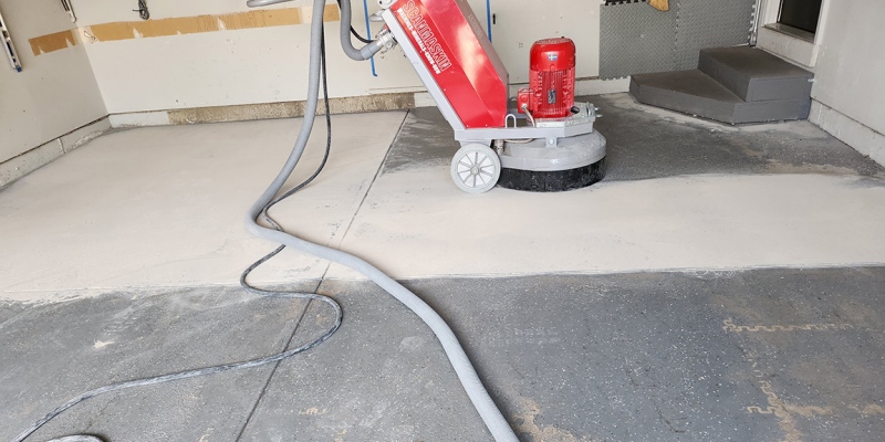
It takes more than simply physical strength to remove stubborn surface coatings like epoxy, glue, and paint from concrete; the proper instruments designed for effectiveness and longevity are needed. Using specialist removal equipment can result in a cleaner, more consistent finish and a significant reduction in labor time, whether you're working on a large commercial space or a private garage.


PCD tools are among the best choices. These instruments are made especially to remove tough coatings without smearing or clogging. PCD segments' aggressiveness enables them to swiftly remove tough adhesives and thick epoxy coatings, revealing a clean surface that is prepared for refinishing. Even in harsh circumstances, their resistance to wear guarantees a long tool life.


EZ Change PCD tools are a notable product on the market because of its rapid mounting mechanism. These tools assist contractors meet deadlines by providing great removal power and enabling quick adjustments on the job site. They work well for both thick and thin coatings, and they can withstand demanding tasks without degrading.


Scanmaskin Combiflex PCD tooling


Husqvarna PCD tooling, which is designed to integrate easily with Husqvarna grinders, is another dependable option. These tools lessen the chance of gouging the concrete by providing a good balance between vigorous removal and surface management. They are a popular choice for contractors looking for accuracy and efficiency, particularly in situations involving professional resurfacing and coating removal.


Scanmaskin Combiflex PCD tooling offers easy handling and strong coating removal for users of Scanmaskin grinders. These tools, which are made especially for Combiflex machines, provide the best contact and stability possible, making them ideal for quickly and easily lifting adhesives, mastic, and several coats of paint.


In addition to expediting the process, selecting the appropriate PCD removal tools for your equipment guarantees a surface that is prepared for polishing or recoating. These tools assist professionals get better results with less downtime when they combine segment design, bond strength, and machine compatibility.

Understanding the Diamond Tool Bonding Process

The effectiveness and longevity of diamond grinding tools are significantly affected by the bonding process that secures the diamond particles. The bonding material serves as the support matrix for the diamonds, influencing their exposure and wear during operation. Consequently, the bond is a vital factor in determining the tool's efficiency, grinding speed, and lifespan on various surfaces.


There are multiple types of bonds typically utilized in diamond tooling, each designed for specific uses. For instance, metal bond diamond grinding discs are perfect for heavy grinding on tough surfaces due to their durability and resistance to wear. In contrast, resin bond diamond polishing tool offers more flexibility for fine polishing, while hybrid floor polishing pads effectively bridge the gap between grinding and polishing stages. Choosing the right bond type is crucial to align the tool with the hardness of the material being processed.


The bond must wear at a controlled pace to continually reveal new, sharp diamonds. For softer materials like green concrete, a hard bond is necessary to avoid quick wear, while a softer bond is more effective on harder surfaces, allowing for efficient diamond release. Incorrect bonding can result in tool glazing or early wear, leading to inefficiency and increased costs.


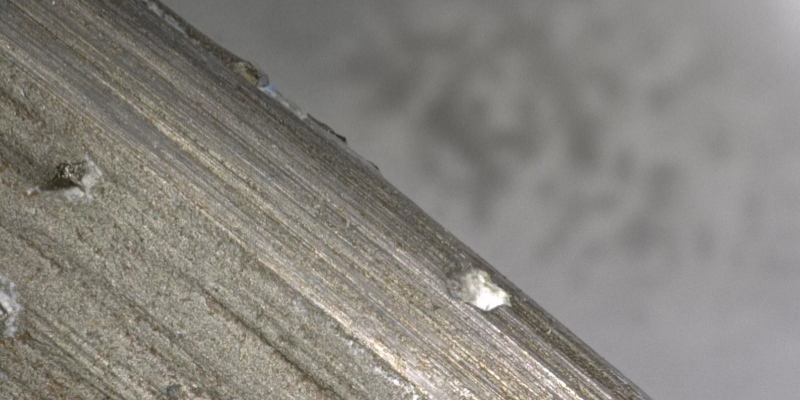
concrete floor diamond grinding tool


Moreover, the concentration and arrangement of diamonds within the bond are critical to performance. A well-balanced bond formula promotes even wear, stable grinding, and uniform surface finishes. This is why professional-grade tools undergo rigorous formulation and testing to meet the specific requirements of different floor conditions and machine compatibility.


At TransGrind, we recognize the essential role of bonding in tool performance. That’s why our diamond tools are crafted with precise bond formulations to guarantee high efficiency, durability, and consistent outcomes in both grinding and polishing tasks. To discover our complete selection of premium diamond grinding tools, please visit us at www.transgrindtools.com.

Can CCS integrated busbars replace the sampling wiring harnesses within battery modules?

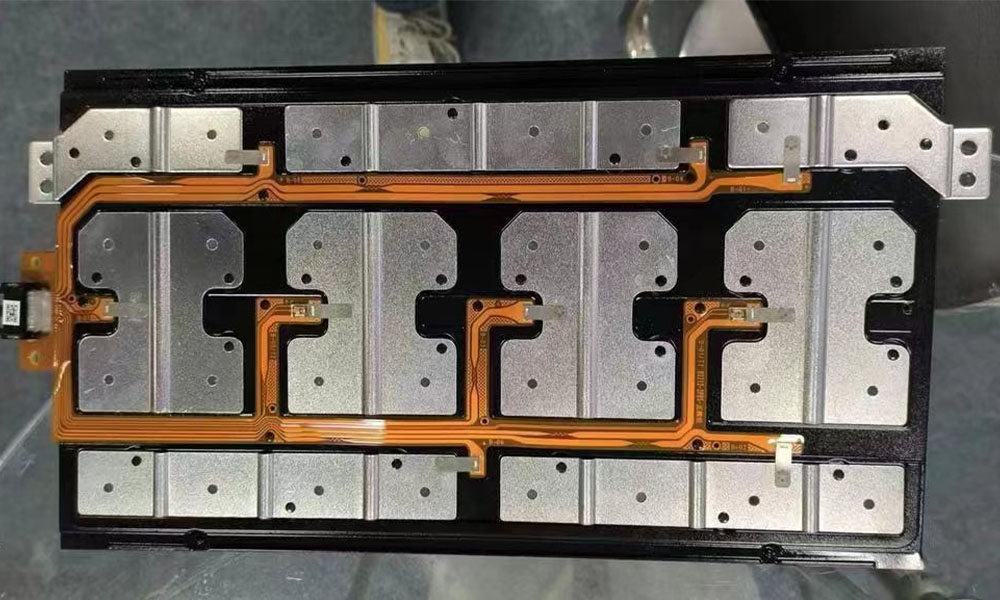
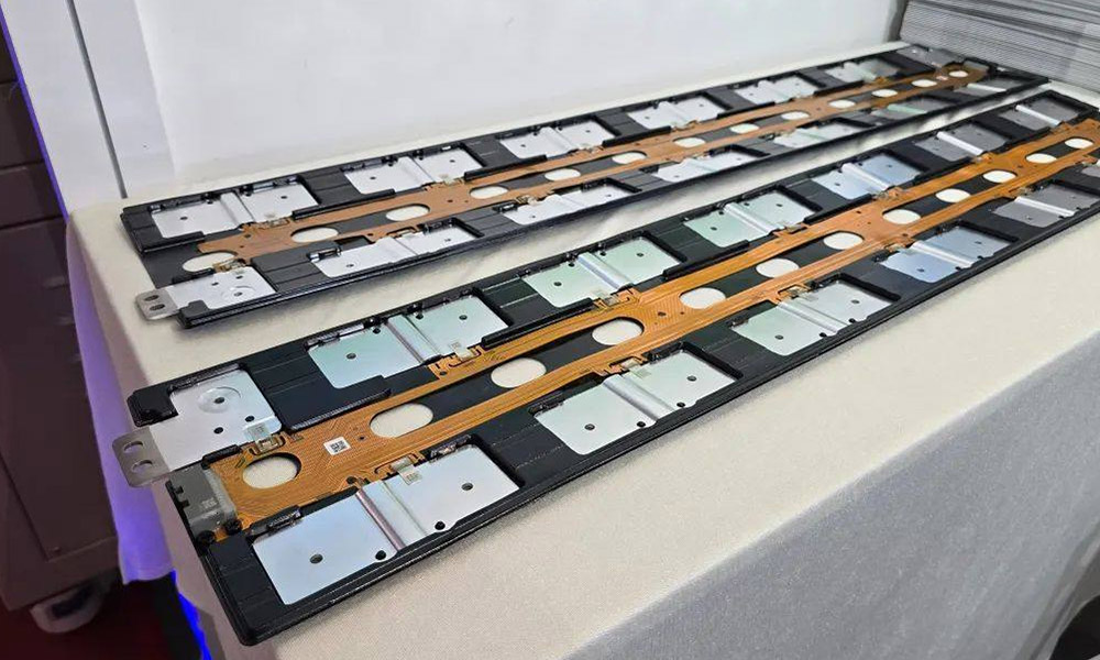
The CCS integrated busbar is mainly composed of signal acquisition components, plastic structural parts, copper and aluminum bars, etc. It is connected into a whole through processes such as hot pressing or riveting. It is applied in new energy vehicles and energy storage battery modules to achieve high-voltage series and parallel connection of battery cells, as well as temperature sampling and voltage sampling of battery cells. And it transmits information such as temperature and voltage to the BMS system through the information sampling component and connector, and is part of the BMS system.

As an important electrical connection component within the battery pack/ module, different cell assembly methods, battery pack calibration parameters, usage environments, as well as requirements for the internal space and weight of the battery pack, will all have different requirements for the sampling component, production process, and material selection of the CCS integrated busbar. Therefore, to meet the diverse demands of the application end, CCS products are constantly upgrading signal acquisition components, optimizing integration processes, etc., and have developed multiple technical routes, including multiple sampling schemes such as wiring harnesses, PCBS, FPCS, FFCS, FDCS, and FCC, as well as multiple integration solutions such as injection-molded brackets, splicing, PET hot-pressed films, and vacuum-formed isolation boards.

Cells Contact System

The current situation of technological development

To meet diverse application requirements, CCS products have developed multiple technical routes:

Sampling schemes: including wiring harnesses, PCBS, FPCS, FFCS, FDCS, FCC, etc

Integrated solutions: covering injection-molded brackets, splicing, PET hot-pressed films, vacuum-formed isolation boards, etc


Characteristics of mainstream integration processes:

Injection molded brackets + riveting process

Material: Flame-retardant PC+ABS or PA66

Advantages: High mechanical strength, good structural strength, and mature and stable technology

Limitations: A heavier product will affect the utilization rate of the internal space of the power battery and the improvement of its driving range. Large-sized forming is difficult, and the development of molds is challenging. The equipment cost is also high

Solution: Splicing isolation. Use several splicing support plates to replace the integrated injection molding brackets to reduce the difficulty of the injection molding process and equipment investment


Vacuum-formed isolation board + hot riveting process

Feature: Flame-retardant PC film vacuum forming

Advantages: Lightweight, low cost, high production efficiency, and high flexibility

Limitations: Relatively poor dimensional stability and relatively poor load-bearing capacity


Hot-pressed insulating film integration

Process: PET insulating film hot-pressing molding

Features: Thin, light and regular structure, high integration, higher stability, and capable of achieving automated assembly

Limitations: Large equipment investment and low production efficiency


Flat plate structure + riveting

Application: Mainly applicable to stationary energy storage

Feature: Prominent cost advantage

Limitation: Relatively weak seismic performance

Overall, different integration processes of CCS integrated busbars each have their own advantages, and the most suitable solution should be selected based on specific application scenarios. For instance, in the field of new energy vehicles, hot-pressing or injection molding solutions can be given priority, while for fixed energy storage, flat plate riveting solutions can be selected.


Aichie is a leading provider of connection solutions in the industry, focusing on producing high-quality connectors, cables and wire harnesses. Aichie has hundreds of skilled employees in two factories, the domestic factory is located in the famous manufacturing city Dongguan City China , and the overseas factory is located in Tan Uyen City, Binh Duong Province, Vietnam. Products are widely used in industries such as Automobiles, Clean Energy, Automation manufacturing, and Smart Homes.

Wire Harness Manufacturers

All products produced by Aichie comply with RoHS2.0 requirements, and some products meet environmental protection requirements such as REACH and halogen-free; Aichie has passed ISO9001, ISO13485, IATF16949 certifications, and is also a UL/CUL/CE recognized manufacturer.

"Quick response, exceeding expectations" is Aichie's business philosophy. Aichie has a professional engineering team, automated production equipment and a flexible production system, which can provide customers with one-stop services from product design, sample verification, production and manufacturing to packaging and shipment.

Welcome to cooperate with us,we will do our best to help you win much more business opportunities!

How much do you know about car wires?

Have you ever felt confused by the intricate wires inside your car when inspecting or repairing it?

The color, cross-sectional area and number of wires all have their specific meanings and standards, which are crucial for ensuring the safe operation of the vehicle's electrical system.


Wire color coding

Wire color coding is a standardized method used to distinguish electrical systems with different functions. This coding system helps avoid incorrect connections during installation, maintenance or repair, thereby improving work efficiency and reducing electrical faults.


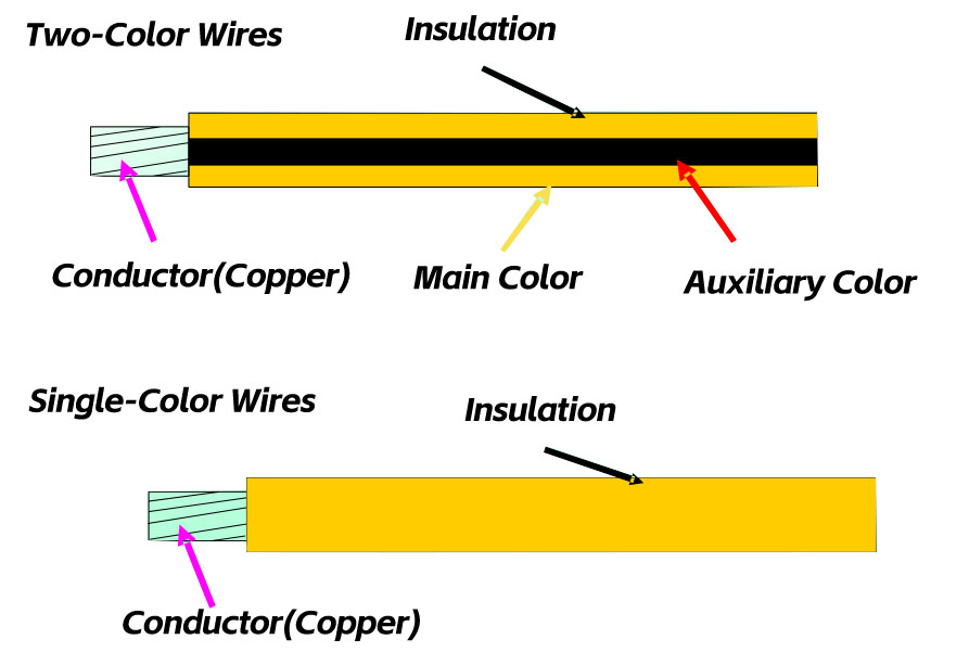
Monochromatic wires and bicolor wires

The insulation layer color of wires is divided into two types: single color and double color.

Monochromatic wire: The insulation layer color is a single color, represented by an English letter. For example, red is represented by "R".

Two-color wire: The insulation layer color is composed of two colors, the main color and the secondary color, with a ratio of the main color to the secondary color of 3:1, represented by two English letters. The first letter represents the primary color and the second letter represents the secondary color. For example, the red and white bicolor wires are represented by "RW".

 Auto Wire Cable

Color code table

The following are some common wire colors and their codes:

Red (R) - RD

White (W) -WH

Black (B) - Bk

Green (G) -Gn

Yellow (Y) -YE

Brown (N) -Br

Blue (U) -Bl

Gray (S) -Gr

Purple (V) - VI

Orange (O) - Or

Pink (P)


Selection of cross-sectional area of wires

The cross-sectional area of the wires selected varies depending on the power of the electrical appliances used. The following are some common circuits and their recommended cross-sectional areas:

Taillights, roof lights, indicator lights, instrument lights, license plate lights, electronic clock: 0.5mm ²

Turn signals, brake lights, distributors, etc. : 0.8mm ²

Headlamp low beam, electric horn (below 3A) : 1.0mm ²

Headlamp high beam, electric horn (3A or above) : 1.5mm ²

Other circuits above 5A: 1.5-4.0 mm²

Electric heating plug: 4-6 mm²

Power cord: 4-25 mm²

Starting circuit: 16-95 mm²


Selection of wire types

Depending on the installation location of the electrical appliances, the types of wires selected also vary. For example:

High-temperature resistant wires should be used in high-temperature areas (such as engine Windows, etc.).

Ordinary wires are used in general areas.


Wire numbering standard

The numbering standard of wires is helpful for identifying the type and specification of wires.

The following are some common wire numbers and their usage standards:

QVR, QVR105: Comply with the JB/T 8139-1999 standard

AVSS, AVS, AVSS105: Comply with the JASO D 611 standard

AV: Complies with the KS C 3311 (JIS C 3406) standard

AEX: Complies with the JASO D 608 standard

QB-B: Complies with the QC/ T730-2005 standard

SHE-K: Shielded wire

 car wiring harness

Now, you should have a deeper understanding of the color coding, cross-sectional area selection and wire numbering standards in automotive wire systems. These standards are crucial for ensuring the safe operation of the vehicle's electrical system. By following these standards, the safety, reliability and maintenance efficiency of automobiles can be enhanced.

It is very important for car manufacturers, maintenance technicians and car owners to understand and comply with these coding standards. This not only helps protect the vehicle, but also contributes to the safety of the driver and passengers. Next time when you face the wires in your car, you will be able to identify and handle them with more confidence.

Technological innovation and performance breakthrough of high-voltage connectors

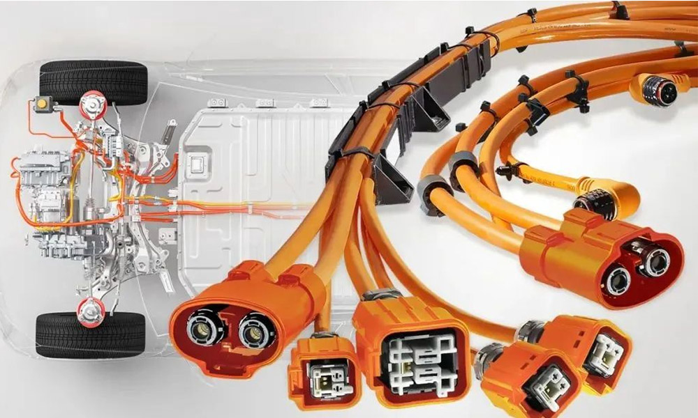
Driven by the dual goals of the "dual carbon" strategy and consumers' range anxiety, automotive lightweighting has become a key technical path for the development of the new energy vehicle industry. As a factory in the wiring harness industry, Aichie Tech has been deeply engaged in the field of new energy vehicle wiring harnesses. Its high-voltage automotive wiring harnesses and high-voltage connector wiring harnesses have demonstrated outstanding performance in lightweight design. Studies show that for every 10% reduction in vehicle mass, energy consumption can be significantly reduced by 6% to 8%, and the driving range can be increased by 5% to 7%. As a core component of the electric drive system, the lightweight design of high-voltage connector harnesses not only concerns the overall vehicle quality optimization but also directly affects the electrical transmission efficiency and system reliability.

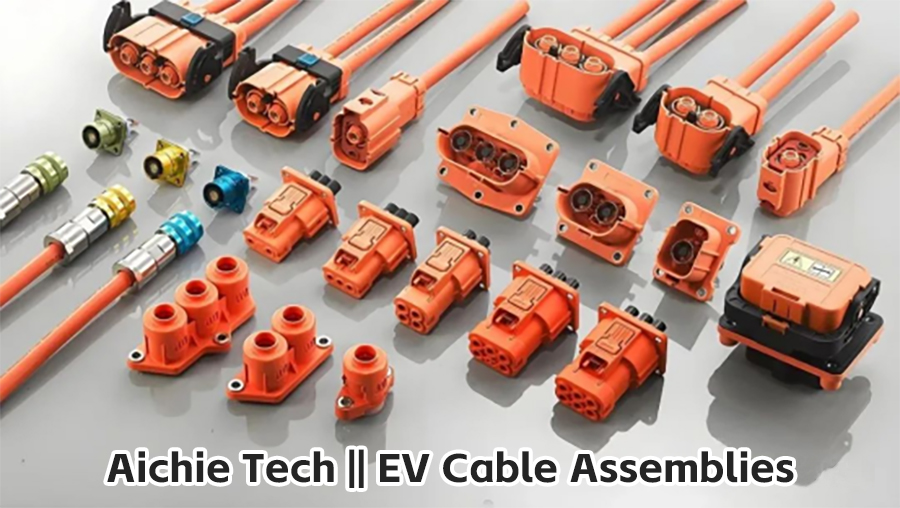
 EV Cable Assembly

I. Material Innovation: The Art of Balancing Lightweight and High Performance

1. Upgrading and iteration of metallic materials

Traditional copper connectors (with a density of 8.96g/cm³) are gradually being replaced by lightweight alloys. Take the AMP+ HVP series of TE Connectivity as an example. It adopts a 6061-T6 aluminum alloy casing combined with copper-silver-plated terminals, achieving a 60% weight reduction effect while ensuring the electrical conductivity. In the research and development of high-voltage connector harnesses, Aichie Tech has also adopted an advanced light alloy material solution. More advanced magnesium alloy die-casting technology, such as a certain product of AVIC Optoelectronics, achieves a 50% weight reduction target while maintaining a tensile strength of 180MPa through topological optimization design.


2. Breakthrough applications of composite materials

In the field of insulators and structural components, high-performance engineering plastics have demonstrated significant advantages. The carbon fiber reinforced plastic housing connector developed by Amphenol, through 30% carbon fiber filling modification, not only enhances the temperature resistance to 150℃, but also achieves an anti-vibration level of 50G (10-2000Hz), reducing the weight by 35% compared to traditional metal solutions. The new energy vehicle wiring harness products of Aichie Tech also adopt a similar composite material solution. Some high-end models use PEEK material, which can still maintain excellent structural stability in a high-temperature environment of 200℃.


II. Structural Optimization: Innovative Practices of System Integration

1.Modular integrated design

Modern high-voltage connector harnesses are developing towards a highly integrated direction. The integrated design solution of a certain German car manufacturer integrates the connector and the shielding layer of the wiring harness. While achieving a 15% weight reduction, it also enhances the EMI shielding efficiency to over 80dB (in the 100MHz frequency band). The high-voltage automotive wiring harness products of Aichie Tech adopt a similar integrated design concept. Yazaki's flat connector solution reduces the volume by 40% compared to the traditional round wire design and is more suitable for the optimized layout of the chassis space.


2. Topology optimization technology

The structural optimization carried out through finite element Analysis (FEA) has achieved remarkable results. A certain domestic connector adopts a grid-like hollow design. 40% of the material is removed in the area where the stress is below 30MPa. After 100,000 vibration tests, it still maintains structural integrity and achieves a 12% weight reduction. The application of bionic design, such as the cross-shaped reinforcing rib structure, achieves mechanical properties comparable to those of the traditional 2mm shell with a wall thickness of 0.5mm.


III. Performance Challenges: Technological Breakthroughs Behind Lightweighting

1. Electrical performance optimization

In response to the limitations of the electrical conductivity of aluminum alloys, the industry has developed a solution that combines multi-strand stranded structures with silver plating processes. A certain Japanese brand has reduced the contact resistance from 8mΩ to below 5mΩ through a silver plating treatment of 5μm or more. Combined with liquid cooling technology, the temperature rise on an 800V platform is controlled within 45K.

2. Improvement in environmental adaptability

In terms of temperature-resistant materials, modified engineering plastics perform outstandingly. A certain type of PBT material filled with a composite of glass fiber and graphene has its temperature resistance improved to 150℃ and its heat distortion temperature reached 200℃. Aichie Tech 's new energy vehicle wiring harness products have also achieved technological breakthroughs in terms of environmental adaptability. In terms of anti-vibration design, through the structural innovation of "combining rigidity and flexibility", the terminal displacement of a certain domestic connector was reduced by 67% in the vibration test, and the contact resistance fluctuation was controlled within 5%.


Conclusion:

The lightweight innovation of high-voltage connector harnesses is a culmination of materials science, structural design and manufacturing processes. As a pioneer in industry technology, Aichie Tech continuously innovates in the fields of new energy vehicle wiring harnesses, high-voltage vehicle wiring harnesses, and high-voltage connector wiring harnesses. With the popularization of 800V high-voltage platforms, connector technology will continue to develop in the direction of being lighter, stronger and more reliable. This lightweight revolution not only promotes the advancement of new energy vehicle technology but also provides key technical support for the low-carbon transformation of the entire transportation sector.

The Current and Future Roles of Connected Cable Assemblies

The Art of Signal Synchronization: Unveiling the Technological Mysteries of Matching Cable Assemblies

In modern electronic systems, signal transmission is like a precise symphony performance. And the matching cable assembly is the indispensable conductor in this performance, ensuring that each electronic signal can be perfectly synchronized and resonate harmoniously.


I. What is a matching cable assembly?

Imagine that in a light show at a large stadium, thousands of LED lights need to flash completely synchronously to present a perfect visual effect. The role of matching cable assemblies in electronic systems is similar - they are specially designed and precisely manufactured RF cables that can ensure that multiple signals maintain strict time synchronization during transmission.

The core technology of these cables lies in "electrical length matching", that is, maintaining a consistent signal transmission time at a specific operating frequency (usually expressed in phase angles). In 5G communication base stations, this synchronization accuracy can reach an astonishing phase difference of less than 1 degree, equivalent to a time synchronization accuracy of several picoseconds (1 picosecond = one trillionth of a second).

II. Why are these components so crucial?

In today's rapidly developing electronic world, matching cable assemblies have become indispensable basic components in many high-tech fields:

Phased array radar system: The phased array radar on modern warships may contain thousands of radiation units, and the signals of each unit must be strictly synchronized. If there is an error in synchronization, it may lead to a deviation in target positioning. After the error is magnified, the difference may be several kilometers.

2. 5G/6G communication networks: Large-scale MIMO antenna systems need to handle hundreds of data streams simultaneously. In the millimeter-wave frequency band, even a difference of a few millimeters in cable length can cause the signal to completely lose synchronization.

3. Satellite communication system: In the geosynchronous orbit at an altitude of 36,000 kilometers, satellites need to maintain precise phase relationships with ground stations. Any signal desynchronization may lead to communication interruption.

4. Medical imaging equipment: MRI (Magnetic Resonance Imaging) machines need to precisely control the phase of radiofrequency signals to reconstruct clear images of human tissues. Phase error can cause artifacts in the image, affecting the accuracy of diagnosis.

III. Manufacturing Process: An art of precision to the extreme

Manufacturing high-quality matching cable assemblies can be regarded as a model of modern precision manufacturing. The entire process requires breaking through multiple technical limits:

Breakthroughs in materials science

Conductor material: Ultra-high purity oxygen-free copper (with a purity of over 99.99%) is used, and the surface is silver-plated to reduce high-frequency loss

Insulating material: Expanded polytetrafluoroethylene (PTFE) is adopted, with a dielectric constant stabilized at 2.1±0.05

Shielding layer: Multi-layer silver-plated copper tape braided, with a shielding efficiency of over 90dB


2. Precision manufacturing process

Length control: Measured by a laser interferometer with an accuracy of ±0.01mm/m

Termination process: The connector is processed by a high-precision CNC machine tool, with a concentricity deviation of less than 0.02mm

Phase matching: Minor differences are compensated through electronic tuning technology, with a matching accuracy of ±0.5°

3. Rigorous testing and verification

Phase stability test: The phase change is less than 2° within the temperature range of -55℃ to +125℃

Mechanical durability test: The performance change does not exceed 1% after 500 insertions and removals

Environmental testing: including multiple rigorous tests such as vibration, shock, and salt spray


IV. Analysis of Typical Application Scenarios

Phased array radar system

In the Patriot air Defense missile system, its AN/MPQ-53 radar contains more than 5,000 radiation units. Each unit requires strict phase control in order to achieve precise beam pointing. The matching cables here ensure that the excitation signals of each unit maintain an accurate phase relationship, enabling the radar to track hundreds of targets simultaneously.

2. 5G Massive MIMO

In the 192-antenna array of 5G base stations, each antenna requires an independent radio frequency channel. After using the matching cable assembly, the system can achieve a phase consistency of ±1°, increasing the spectral efficiency by more than three times.

3. Quantum communication system

In quantum key distribution systems, signals at the single-photon level need to maintain precise phase relationships. The specially designed matching cable can control the signal loss within 0.1dB/m while maintaining phase stability.


V. Future Development Trends

With technological advancements, matching cable assemblies are developing rapidly in three directions:

Higher frequency: Supports the 110GHz TeraHertz frequency band, with phase stability better than ±0.5°

2. Smaller size: Develop miniaturized solutions, with ultra-fine matching cables with a diameter of less than 1mm

3. More intelligent: Integrating temperature sensors and compensation algorithms to achieve real-time phase calibration


It is particularly worth mentioning that in the upcoming 6G era, terahertz communication poses more stringent requirements for the corresponding cables. Researchers are developing new cable structures based on novel metamaterials, which are expected to achieve breakthrough performance in the 300GHz frequency band.


Conclusion

From deep-sea probes to deep-space telescopes, from smart phones to smart healthcare, the matching cable assemblies silently support every significant breakthrough in modern technology. They may be hidden inside the devices and not seen by others, but it is precisely these precise components that ensure our digital world can operate precisely and reliably.

With the development of new technologies such as the Internet of Things and artificial intelligence, the requirements for signal synchronization accuracy will only become higher and higher. The technological innovation of matching cable assemblies will continue to drive the pace of human technological progress.

What are shielded cables?

What is a shielded wire?

Definition: A wire with a conductor wrapped around the outside is called a shielded wire. The wrapped conductor is called a shielding layer, which is generally a braided copper mesh or copper foil (aluminum). The shielding layer needs to be grounded, and external interference signals can be conducted into the earth through this layer.


Function: To prevent interference signals from entering the inner layer, avoid conductor interference, and reduce the loss of the transmitted signal at the same time. Structure: (Common) Insulation layer + shielding layer + wire (advanced)

Insulation layer + shielding layer + signal conductor + shielding layer grounding conductor

Note: When choosing shielded wires, the shielding layer grounding wire. The insulating layer of the shielding layer grounding wire has a conductive function and can conduct electricity with the shielding layer (with a certain resistance).


The principle of shielded cables

The shielded cabling system originated in Europe. It is a common unshielded cabling system with a metal shielding layer added outside. By taking advantage of the reflection, absorption and skin effect of the metal shielding layer, it achieves the function of preventing electromagnetic interference and electromagnetic radiation. The shielded system comprehensively utilizes the balance principle of twisted-pair cables and the shielding effect of the shielding layer, thus having very good electromagnetic compatibility (EMC) characteristics.


The balance characteristics of U/UTP(unshielded) cables do not only depend on the quality of the components themselves (such as twisted pairs), but are also affected by the surrounding environment. Because the metal around U/UTP (unshielded), concealed "ground", pulling, bending and other conditions during construction can all disrupt its balance characteristics, thereby reducing the EMC performance. Therefore, to achieve a lasting and unchanging balance characteristic, there is only one solution: to ground all the core wires by adding an extra layer of aluminum foil. Aluminum foil adds protection to the fragile twisted-pair core wire while artificially creating a balanced environment for U/UTP (unshielded) cables. Thus, what we now call shielded cables are formed.


The shielding principle of shielded cables is different from the balance cancellation principle of twisted-pair cables. Shielded cables add one or two more layers of aluminum foil outside the four pairs of twisted-pair cables. They utilize the reflection, absorption of electromagnetic waves by metals and the skin effect principle (the so-called skin effect refers to the distribution of current across the cross-section of a conductor tending to the surface of the conductor as the frequency increases. The higher the frequency, the smaller the skin depth, that is, the higher the frequency, the deeper the skin The weaker the penetrating power of electromagnetic waves, the more effectively it can prevent external electromagnetic interference from entering the cable, and at the same time, it can also prevent internal signals from radiating out and interfering with the operation of other equipment.

Experiments show that electromagnetic waves with frequencies exceeding 5MHz can only pass through aluminum foil 38μm thick. If the thickness of the shielding layer exceeds 38μm, the frequency of electromagnetic interference that can penetrate the shielding layer and enter the interior of the cable will mainly be below 5MHz. For low-frequency interference below 5MHz, the balance principle of twisted-pair cables can be effectively applied to cancel it out.


According to the earliest definition of wiring, it is divided into two types: unshielded cables -UTP and shielded cables -STP. Later, with the development of technology and the different processes of various manufacturers, many different types of shielding have emerged

1. F/UTP Foil Screened Cable single-layer foil shielding structure

2. Foil and Braid Screened Cable foil and copper braided mesh double-layer shielding structure

a)SF/UTP aluminum foil and copper woven mesh are simultaneously wrapped around the outer layers of the four pairs of wires

b)S/FTP (PIMF) wire pairs: Single Pair aluminum Foil shielding plus copper braided mesh wrapped around the outer layer of the four pairs of wires. PIMF =Pair in Metal Foil.

The resistance of shielded cables to external interference is mainly reflected in the fact that the integrity of signal transmission can be guaranteed to a certain extent through the shielding system. The shielded wiring system can prevent the transmitted data from being affected by external electromagnetic interference and radio frequency interference. Electromagnetic interference (EMI) is mainly low-frequency interference. Motors, fluorescent lamps and power cables are common sources of EMI. Radio Frequency Interference (RFI) is high-frequency interference, mainly wireless frequency interference, including radio, television broadcasting, radar and other wireless communications.

For resisting electromagnetic interference, braided layer shielding is the most effective choice, that is, metal mesh shielding, because it has a relatively low critical resistance. As for radio frequency interference, metal foil shielding is the most effective, because the gaps created by metal mesh shielding allow high-frequency signals to enter and exit freely. For interference fields with mixed high and low frequencies, a combined shielding method of metal foil layer and metal mesh should be adopted, that is, a double-layer shielded cable in the form of S/FTP. This enables the metal mesh shielding to be suitable for low-frequency range interference and the metal foil shielding to be suitable for high-frequency range interference.


The single-layer thickness of the aluminum foil shielding layer in the shielded cables of IBM ACS reaches 50-62μm, achieving a more complete shielding effect. At the same time, as only a single layer of shielding is adopted, it will be simpler for construction, easier to install, less likely to cause man-made damage during the construction process, and the thickness of the aluminum sheet can withstand greater destructive force. Thus, it can provide users with higher-quality transmission performance.

What impact does the development of new energy vehicles have on the demand for wiring harnesses?

The rapid development of new energy vehicles is reshaping the automotive industry chain pattern, and the wiring harness system, as the "nervous system" of vehicles, has also undergone profound changes in its technical demands and market structure. From high voltage, intelligence to lightweighting, the wire harness industry is undergoing an all-round upgrade from material innovation to manufacturing models. This article will analyze the core impact of new energy vehicles on the demand for wiring harnesses from three dimensions: technological evolution, market landscape, and future trends.


The revolution of high-voltage drive technology

The popularization of 800V high-voltage platforms

The trend of high voltage in new energy vehicles is significant. The popularization of 800V platforms (such as Porsche Taycan and XPeng G9) has driven the voltage resistance level of wiring harnesses to increase from the traditional 600V to over 1500V. High-voltage wiring harnesses need to adopt new technologies such as silicone insulation and three-layer shielding structure to suppress partial discharge and electromagnetic interference (EMI), while meeting the ISO 26262 functional safety standard.

Material breakthrough: Cross-linked polyethylene (XLPE) and ceramic nanocomposites have been widely applied, and the temperature resistance grade has been raised to 200℃.

Liquid cooling technology: The liquid-cooled charging gun wiring harness of the Porsche Taycan can achieve a continuous current of 500A, with temperature rise controlled within 30K.


The market has exploded

In 2022, the market size of high-voltage wiring harnesses in China was 14.14 billion yuan. It is expected to reach 23.8 billion yuan by 2025, with a compound annual growth rate of 28%. Globally, the market size of high-voltage wiring harnesses is expected to exceed 18 billion US dollars by 2025, with China accounting for 45%.


Intelligence and architecture Reconfiguration

Transformation of electronic and electrical architecture

The application of the Zonal Architecture significantly reduces the length of the wiring harness (for example, the wiring harness of Tesla Cybertruck is shortened to 100 meters), but the problem of cross-domain signal synchronization needs to be solved. In-vehicle Ethernet (with a bandwidth of 10Gbps) is gradually replacing CAN bus and becoming the core of intelligent driving data transmission.


The demand for sensors has soared: The number of sensors in L3+ autonomous driving models has exceeded 30, and the demand for dedicated optical fiber harnesses for lidar has increased by 62% annually.


Lightweighting and cost challenges

Material substitution and process innovation

Aluminum wire substitution: The electrical conductivity of aluminum wire reaches 97% of that of copper, its weight is reduced by 30%, and its cost is cut by 40%. By 2025, its application proportion is expected to reach 22%.

Carbon fiber composite material: The weight of the sheath is reduced by 60%, helping to reduce the overall vehicle weight by 10% to 15%.


Cost pressure and automation upgrade

Raw material costs account for 65% to 80% of the total cost of wiring harnesses, among which copper materials have the highest proportion. By means of automated production (crimping accuracy ±0.1mm) and digital twin technology, the automation rate of domestic wire harness factories will reach 75% by 2025, and labor costs will be reduced by 40%.


Reconstruction of the supply chain ecosystem

The acceleration of domestic substitution

Foreign manufacturers (such as Yazaki and Aptiv) have long held over 70% of the market share. However, domestic enterprises like Huguang Co., Ltd. and Kabeiyi have increased their market share from 3% to 28% through technological breakthroughs (such as high-voltage wire harnesses withstand 1000V) and customer expansion (entering the supply chains of Tesla and BYD).


Standardization and modularization

Byd e-Platform 3.0 has reduced the number of connector types from 120 to 30, increasing assembly efficiency by 25%. Aptiv's Intelligent Automotive Architecture (SVA) drives wiring harness suppliers to transform towards modular system integration.


Future trends: Intelligence and sustainability

Intelligent wiring harness system

Embed fiber Bragg grating sensors to monitor temperature and strain in real time; Self-healing material technology can extend the lifespan of wiring harnesses by 30%.


Green manufacturing

The EU's "New Battery Regulation" requires that the recycling rate of wiring harnesses exceed 95%, and the carbon footprint of bio-based materials (such as BASF Ultramid® Bio) be reduced by 60%, which has been applied to the SAIC IM Motors L7.


Wireless exploration

The BMW iX reduces the number of door wiring harnesses by 12 through UWB technology, but the backbone network still relies on wired transmission. It is expected that by 2025, the proportion of the "wired + wireless" hybrid architecture will exceed 80%.


The explosive growth of new energy vehicles has driven the wiring harness industry to leap from traditional manufacturing to a high-tech intensive industry. Future competition will focus on materials science (such as superconducting technology), intelligent manufacturing (such as AI quality inspection), and ecological collaboration capabilities. Domestic manufacturers are gradually breaking the monopoly of foreign capital through technological breakthroughs and supply chain integration. This transformation is not only an iteration of technology, but also a crucial battle for the redistribution of value in the global automotive supply chain.

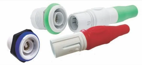
What is a reusable connector?

Reusable and limited-reuse connectors must perform the same work as the reusable version, but cost, functionality and environmental impact play a greater role in their design. Reusable products are mainly applied in the medical field, maximizing patient safety by preventing cross-contamination and infection. They are also used in food processing, research laboratories and industrial processes that require a sterile environment.


FDA regulations, EPA restrictions, Reach and RoHS compliance, the use of hazardous materials or conflict minerals can all affect the manufacture of a device that provides a high level of care. Important considerations for reusable connectors include:

Safety

Cleaning

Reliability

Cost per use

Be capable of combining one-time use with limited reuse or reusable components

The trend towards higher voltage and higher density

For example:

The HyperGrip series of Smiths Interconnect includes disposable plugs and sockets suitable for HG2 and HG4 sizes. They are designed to support over-molding and high-capacity production methods. They can withstand at least 30 cycles while ensuring the insulation resistance, dielectric withstand voltage, current carrying capacity and low-level current resistance performance of the connectors. HyperGrip is a circular plastic, user-configurable, color-coded connector with a push-pull lock design that allows for one-handed disconnection. HyperGrip is designed to meet the requirements of the medical industry, such as fing-proof design in compliance with IEC 60601, UL94 flame retardant grade, and compatibility with most sterilization requirements.


Design Description

Standards: FDA, EPA, Reach, RoHS, IEC 60601, UL, CSA

Pairing cycle: A limited number of pairing cycles, typically 10 to 30 times.

Connection methods: locking type, non-locking type, breakable type


Contact pieces: According to performance requirements, applicability for specific applications, and cost-effectiveness, helical hyperbolic contact systems, stamped hyperbolic contact pieces, edge card contact pieces, and spring probes are usually selected. Pneumatic and fluid contact parts are used to handle gases, brine or suction. Optical fiber contacts for imaging, sensing and data transmission are crucial for many emerging technologies; However, its cost and complexity are quite high.


Termination: To reduce costs while maintaining performance, a more economical termination method than welding may be used.


Material specifications: Material selection must strike a balance between cost-effectiveness, durability and chemical compatibility. The shell and components are made of plastics and thermoplastics, such as polybutylene terephthalate (PBT), polycarbonate (PC), acrylonitrile-butadiene-styrene (ABS), polyvinyl chloride (PVC), and polyurethane (PUR). In medical applications, for instance, polyetheretherketone (PEEK) and polyarylsulfone (PPSU) are used due to their resistance to sterilization and chemicals.


Environmental characteristics: Anti-fingerprint (conforming to IEC 60601 standard), flammability grade (UL94), ethoxyethane sterilization, secondary injection molding


The protection level depends on the specific application and environmental conditions. For example, the HyperGrip protection level of Smith Interconnect is IPX4.


Market

Medical care, industry


Application

Medical applications (e.g., electrocardiogram, endoscopy), food processing, research laboratories