High voltage wire harness is an important carrier of the power and signal transmission and distribution system of new energy vehicles, and the crimping performance of high voltage wire harness terminals is the most important performance index of new energy vehicles. This paper establishes a data analysis model for the crimping performance of high voltage wire harness terminals of new energy vehicles, and finds out the best adaptation range of the compression ratio of high voltage wire harness terminals by analyzing relevant data, so as to improve the process capability and quality level of high voltage wire harness cold crimping.
With the rapid advancement of the country's new energy automobile industry, it has brought major opportunities to the development of new energy wiring harnesses. The difference between high-voltage wire harness and low-voltage wire harness terminals is that high-voltage terminals tend to generate heat due to the large current passing through them, which leads to the decrease of terminal mechanical strength and wire harness insulation performance, and causes conductor oxidation to further aggravate heat and other problems. High voltage terminal crimping needs to consider not only the reliability of crimping, but also the low temperature rise at the crimping area. This paper mainly studies the effect of cold crimping on terminal temperature rise.
01 Crimp type
High voltage terminals are commonly connected by crimping, resistance welding, and high frequency welding. Crimping equipment and dies are used to connect wires and terminals together through a crimping process. High-frequency welding is the use of high-frequency welding machine wire and terminal welding together. Resistance welding is the use of special resistance welding equipment to connect wires and terminals together.
This paper mainly analyzes the performance of crimping. The advantages of ordinary crimping: simple operation, easy use and maintenance, low manufacturing cost, high operational efficiency, suitable for mass production. Disadvantages: The wiring harness and terminals that require high current pass rate and small resistance after the connector requires the wire and terminal to be connected cannot be met.
The common crimping mode of the large square high voltage terminal is shown in Figure 1, which is a hexagonal closed terminal. The advantages of ordinary crimping are obvious, but it is particularly important to minimize the resistance of ordinary crimping. Reducing resistance means reducing heat, reducing product temperature rise, and making product life and quality better.

02 terminal heating hazards
After the terminal is heated, it is easy to oxidize itself and the contact surface of the conductor, forming an oxide film, which increases the contact resistance, and the increasing speed increases exponentially with the increase of temperature, further increasing the temperature rise speed of the terminal, which will cause a fire in serious cases. At the same time, the elastic element of the contact structure will be annealed, the contact pressure will be reduced, and the contact resistance will be further increased. In addition, the heat will make the insulation layer of the wire connecting the terminal aging brittle, causing the insulation performance to decline, there is a risk of leakage overheating caused by fire.
03 Heat source of terminal
As shown in Figure 2, the high voltage harness has three heat sources.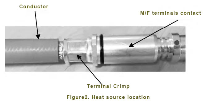
3.1 Conductor
The conductor itself has resistance, the smaller the cross-sectional area, the higher the resistance, and the resistance will cause heating.
3.2 Terminal crimping
If the compression ratio is not enough, the conductor will be loose, resulting in large resistance and easy heating. Excessive crimping is easy to cause the cross-sectional area to become smaller, and the carrying current is not enough to cause heat.
3.3 Contact of male and female terminals
The terminal contact is poor, or the contact surface of the terminal is oxidized, resulting in serious heating.
04 Method to reduce the terminal temperature
4.1 Reduce contact resistance
(1) Materials with low resistivity are used. Commonly used high-voltage terminals are H62, H65 copper, or high-conductivity copper. For products larger than 125 A, it is recommended to use high-conductivity copper with low resistivity.
(2) Reduce the contact resistance of the conductor. Compact the terminal and conductor as much as possible to reduce the crimping resistance.
(3) Increase the cross-sectional area of the conductor, increase the cross-sectional area, and reduce the temperature rise of the wire.
4.2 Increase the heating area of the conductor
(1) Forced cooling, air cooling, water cooling and other measures can be used.
(2) Reasonable arrangement of conductors, wiring harnesses with large current, as far as possible arranged in a space that is easy to dissipate heat, conducive to natural heat dissipation.
05 Effect of crimping on temperature rise
For crimping, refer to the 4.2.6 voltage drop test requirements in QC/T 29106-2014 "Automotive Wiring Harness Technical Conditions" [1] and the temperature rise test requirements in GB/T 20234.1-2015 "Connection Devices for conductive Charging of electric vehicles Part 1 General Requirements" for verification. The process is shown in FIG. 3 and FIG. 4. The obtained data are shown in Table 1.
 |
 |
5.1 Compression ratio/Compression ratio calculation method
(1) Refer to VW60330-2013 standard
Where, Acrimp is the cross-sectional area of the conductor contained in the crimp; Aconductor is the nominal cross-sectional area of the conductor.
(2) Refer to SAE/ USCAR21-2014 standards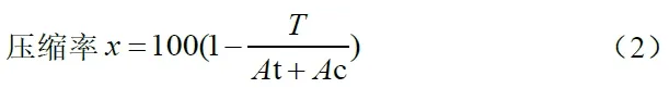
Where, T is the area retained when the crimp blade is closed; At is the cross-sectional area of the nominal terminal; Ac is the cross-sectional area of the nominal conductor.
(3) The difference between conductor compression ratio and terminal compression ratio
According to VW 60330-2013 [4] standard, the calculation of compression ratio only includes the compression of the conductor without the terminal, which can directly reflect whether the conductor has a gap. When the compression ratio is less than 100%, there should be no gap. We can call it the wire compression ratio.
According to the SAE/ USCAR21-2014 standard, the calculation of the compression ratio includes the compression of the conductor and the terminal, which cannot directly reflect whether there is a gap in the conductor, but can directly reflect the real cross-sectional area of the compression joint. In order to facilitate data comparison, this article defines the terminal compression ratio =100T/ (At+Ac).
Both calculation methods have their own advantages.
5.2 Analysis Results
(1) As shown in Table 1, when the conductor compression ratio of product 3# reaches 104%, the pulling force has reached the standard of 50 mm2 stipulated in QC/T 29106-2014, and the conductor pulling force is ≥2 700 N, but at this time, the compression joint has not been fully compacted, and there are large safety risks. Therefore, the tension of the high voltage terminal can not be used as a standard to judge the quality.
(2) The resistance value in the table is not completely corresponding to the temperature rise trend, which should be caused by the difference in the contact resistance of the terminal individual and the inconsistency caused by the oxidation of the terminal coating. However, from the general trend, it basically conforms to the corresponding relationship of lower resistance and lower temperature.
(3) The compression ratio of the 7# terminal is 73%, and there is an oxide layer on the surface of the conductor and the terminal, which will gradually be destroyed with the reduction of the compression ratio value. When the compression ratio of the terminal is 73%, the oxide layer of the conductor begins to collapse, which makes the copper wire fuse more tightly and the temperature rise is slightly reduced, indicating that the terminal compression comparison is appropriate at this time.
(4) From the point of view of temperature rise value fluctuation, the impact of crimping on temperature rise can reach 10 ℃. This has a greater impact on the crimping of high voltage terminals.
(5) 10# Product terminal compression ratio At 60%, the theoretical cross-sectional area of the conductor at the terminal crimp is only 30 mm2, according to SAE/ USCAR21-2014 terminal compression ratio calculation, the cross-sectional area at the crimp in addition to the conductor, the cross-sectional area of the terminal should also be included. The actual cross-sectional area between the crimped conductor and the terminal is 66.97 mm2, which is greater than the nominal cross-sectional area of the conductor of 50 mm2. Therefore, the compression ratio does not cause a bottleneck at the compression area, and is in line with the actual situation. In addition, the calculation method of the terminal compression ratio is more suitable for high-voltage terminals.
(6) Too low compression ratio will cause the temperature rise at the crimp joint to be too high. According to the actual measurement, when the terminal compression ratio reaches below 40%, the terminal crimp resistance will gradually increase. The terminal temperature rise began to rise slightly.
(7) Terminal compression ratio analysis for hexagonal crimp terminals. First of all, no matter what the cross-sectional area of the pressure junction should not be less than the nominal conductor cross-sectional area; Secondly, due to the material thickness selection of each high-voltage terminal will be different, according to the terminal compression ratio =100T/(At+Ac), some terminals have a low At cross-sectional area, after compression, too low terminal compression ratio will cause the cross-sectional area of the crimp is less than the nominal conductor cross-sectional area. Therefore, the cross-sectional area after crimping needs to be as large as possible. In addition, if the compression ratio is too low, the mechanical tension value of the terminal will decrease, which will affect the reliability of the terminal crimping.
06 Conclusion
Based on the above analysis, consider the reliability of terminal crimping strength and terminal resistance. The actual terminal compression ratio is controlled at 65% ~ 75%, and the conductor compression ratio is 65% ~ 80%. In addition, from the experimental data, some of the resistance and temperature rise data fluctuations are related to the coating and oxidation of the terminal and the contact structure of the terminal, so it is not enough to reduce the temperature rise from the perspective of crimping quality alone. It is necessary to pay special attention to the daily preservation of the terminals, the quality of the coating of the terminals, and the life of the terminals, the insertion force, and the contact area.
For products with large temperature rise, it is recommended to use high-frequency welding, which makes copper heat through friction at ultra-high frequencies, melting copper and bonding, which has lower resistance, so it has a better effect in controlling temperature rise.
Aichie Tech provides auto wiring harness , high voltage ev cable assembly and low -voltage auto wiring harness around the world. It has introduced new production equipment, which greatly improves the quality and efficiency of production. Customers are widely distributed in Europe and North America. Production employees and experienced engineering teams and sales teams serve our customers; please contact us now! We will provide you with competitive prices!
WeChat: 180 2750 2150
Tel: +86 180 2750 2150